Substation Grounding
The main objective of a Substation Grounding Study is to design safe grounding facilities for substations and buildings.
The way we proceed:
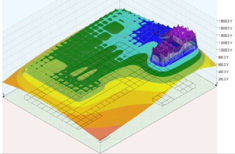
We first use soil resistivity measurements to calculate a 2-layers or multilayer soil model ; also, the maximum allowable step and touch voltage are calculated according to IEEE or EN Standard.
Then the geometry of the ground grid is accurately modeled or imported from CAD software (.dwg or .dxf format).
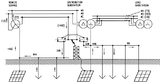
Finally, we apply the maximum LG fault current on the substation, then we evaluate the step and touch voltages over the substation. We then compare them to the maximum allowable values calculated before, according to the IEEE or EN Standards.
In case safety conditions are not garanteed over the substation, different optimisation methods will be checked such as:
- Increasing the total length of grounded conductors (improved meshing),
- Increasing the depth of grounded conductors,
- Adding rods (vertical grounded conductors).
- Adding high resistivity material such as gravel at the surface of the substation.
We can carry out on site measurements to obtain the missing equipment parameters and validate the simulation model.


